
MySQL Logs#
There are actually many types of logs, but the more important ones for interviews are:
- Bin log (belongs to MySQL)
- Undo log
- Redo log
In my impression, it seems only undo log and redo log belong to InnoDB, while the others belong to MySQL.
Undo log - InnoDB#
Actually, this isn’t very specific yet. For details, you can refer to the JavaGuide article. For now, understanding up to this point is sufficient.
Main functions:
- Provides rollback functionality for MySQL transactions, used to achieve transaction atomicity.
- Used together with ReadView to implement the MVCC mechanism.
How Rollback Works#
Regarding rollback, it’s actually quite intuitive:
- For Insert, Delete, and Update operations, they can be explained according to our “intuition”.
- For the Delete operation, the record is not actually deleted immediately but is marked for deletion. The final deletion is carried out by the purge thread.
- For the Update operation:
- If the operation target is a primary key column, the row is deleted first, and then the target row is inserted.
- If it is not a primary key column, the reverse is recorded (i.e., the original row is logged).
Each update operation generates an undo log record containing roll_pointer and trx_id, meaning:
- The transaction ID indicates which transaction made the change.
- The rollback pointer links these undo logs into a linked list, forming a version chain.
Regarding the MVCC mechanism, refer to MySQL Locks section:#
- RC: A new snapshot is generated for each query.
- RR: A new snapshot is generated for each transaction.
The MVCC mechanism needs review.
Regarding the Persistence of Undo Log:#
The persistence strategy for undo log is the same as for data pages; its durability is guaranteed by redo log.
Modifications to undo log pages in the buffer pool are recorded in the redo log. The redo log (explained in detail below) uses its own mechanism to flush to disk.
Buffer Pool - InnoDB#
The cache pool: Caches modified records, allowing direct reads from the cache instead of going to disk, used to improve database read/write performance.
- Reading Data: If the data exists in the buffer pool, read it directly; otherwise, read it from disk.
- Modifying Data: If the data exists in the buffer pool, directly modify the page containing the data in the cache pool and mark the page as a “dirty page”.
- To optimize disk I/O, dirty pages are not flushed to disk immediately. A background thread flushes them at an appropriate time.
When Dirty Pages are Flushed to Disk:#
- When the redo log is full, triggering dirty page flush automatically.
- When buffer pool space is insufficient, requiring eviction of some pages. If a page is dirty, it must be flushed to disk first.
- During idle periods, a background thread periodically flushes dirty pages to disk.
- Before MySQL shuts down normally, all dirty pages are flushed to disk.
If SQL execution occasionally takes longer, it might be due to the performance overhead of flushing dirty pages to disk, causing database operation jitter. This can be mitigated by increasing the buffer pool or redo log size.
Buffer Pool Structure:#
It uses the data page as its basic unit (default 16KB). Pages within the Buffer pool are called cache pages.
Types of pages in the buffer pool roughly include:
- Data pages, Index pages, Insert buffer pages, Undo pages, Adaptive Hash Index, Lock information.
- Undo pages: Store the corresponding undo log.
- When querying a record, InnoDB loads the entire data page into the buffer pool and then locates the specific record via the Page Directory within the data page.
++Q: Is the Undo page in the Buffer Pool the primary storage location for undo log? Are there other storage locations?++
By default, the buffer pool is a contiguous 128MB block of memory allocated from the operating system (adjustable via innodb_buffer_pool_size).
To manage cache pages more effectively, the buffer pool creates a control block for each cache page (containing tablespace ID, page number, address, linked list node pointers, etc.):
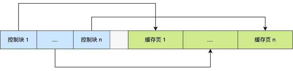 The empty space in the middle is fragmentation (space not large enough for a pair of control block + cache page).
The question arises: How do we quickly find a free page? We can’t traverse the entire memory space to find a free cache page (very inefficient).
So, the Free linked list structure is used:
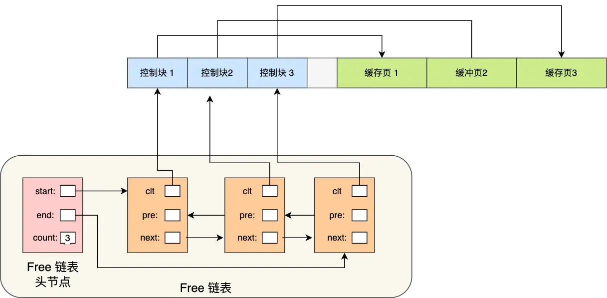 With the free list, whenever a page needs to be loaded into the cache pool, a free cache page is taken from this list, filled with the page information, and then removed from the list (as this cache page is no longer “free”).
Another question: How to quickly find dirty pages?
To quickly identify dirty pages, the flush linked list is used:
 Similar structure to the free list. A background thread can directly traverse this list to write dirty pages to disk.
How to Improve Cache Hit Rate?#
Since the buffer pool size is limited, how can we maximize the cache hit rate?
- The LRU algorithm comes to mind, but it’s not a simple LRU.
- A simple LRU algorithm cannot avoid:
- Read-Ahead Failure: Based on spatial locality, adjacent data pages are loaded to reduce disk I/O, but these preloaded pages might never be accessed. This can cause frequently unused pages to stay at the front of the LRU list, while frequently used ones might be evicted.
- Solution: Allow pre-read pages to stay for as short a time as possible. Move them to the head only when actually accessed, allowing truly hot data to stay longer.
- Divide the LRU list into
oldandyoungregions: Pre-read pages are added to the head of theoldregion. When actually accessed, they are moved to the head of theyoungregion. Theold:youngratio can be set viainnodb_old_blocks_pct.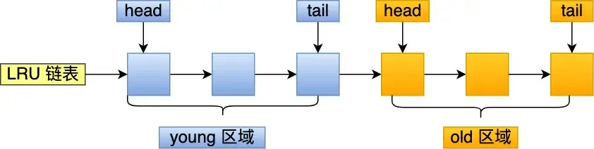
- Buffer Pool Pollution: Due to limited buffer pool space, a SQL statement scanning a large amount of data might evict all pages from the buffer pool. When hot data needs to be accessed again, cache misses occur, leading to massive disk I/O.
- Solution: Raise the barrier for entering the
youngregion to ensure data in theyoungregion isn’t easily replaced. - When a cache page in the
oldregion is accessed for the first time: Entering theyoungregion requires checking the time spent in theoldregion. If the dwell time reaches a certain threshold (defaultinnodb_old_blocks_time= 1000ms), it can be moved to the head ofyoung. Condition: “accessed” + “stayed in old region for more than 1 second”. - In MySQL, accesses to the first 1/4 of the
youngregion do not cause movement to the list head; only accesses to the latter 3/4 do.
- Solution: Raise the barrier for entering the
- Read-Ahead Failure: Based on spatial locality, adjacent data pages are loaded to reduce disk I/O, but these preloaded pages might never be accessed. This can cause frequently unused pages to stay at the front of the LRU list, while frequently used ones might be evicted.
- A simple LRU algorithm cannot avoid:
- The buffer pool manages pages using three lists:
- free page: Located in the free list.
- clean page: Located in the LRU list.
- dirty page: Exists in both the LRU list and the flush list.
Redo log - InnoDB#
Mainly used to achieve transaction durability (it feels like all the work done serves the purpose of “flushing to disk”).
「WAL (Write-Ahead Logging)」: MySQL write operations are not written to disk immediately; they are written to a log first, and then to disk at an appropriate time.
Through redo log + WAL, it can be ensured that even if the database encounters an exception, already committed transactions will not be lost, i.e., crash-safe.
Specific Content of Redo Log:#
Redo log is a physical log: it records what modifications were made to a specific page (made AAA update at ZZZ offset on YYY data page in XXX tablespace). Executing a transaction generates one or more physical log entries.
Some Common Questions:#
- Both redo log and undo log seem capable of “recovering” database content? So what’s the difference?
- Undo log is used for transaction rollback when a specific transaction encounters a problem or crashes, ensuring transaction atomicity (i.e., it records the state of data before modification).
- Redo log is used for crash recovery of transactions, ensuring transaction durability (i.e., it records the state of data after modification).
- Both redo log and data are written to disk, so why this extra step?
- It transforms write operations from random writes to sequential writes, improving write performance.
- Writing to redo log is always an append operation (sequential write).
- Writing data requires finding the write location first, then writing to disk (random write).
- It achieves transaction durability, giving MySQL crash recovery capability.
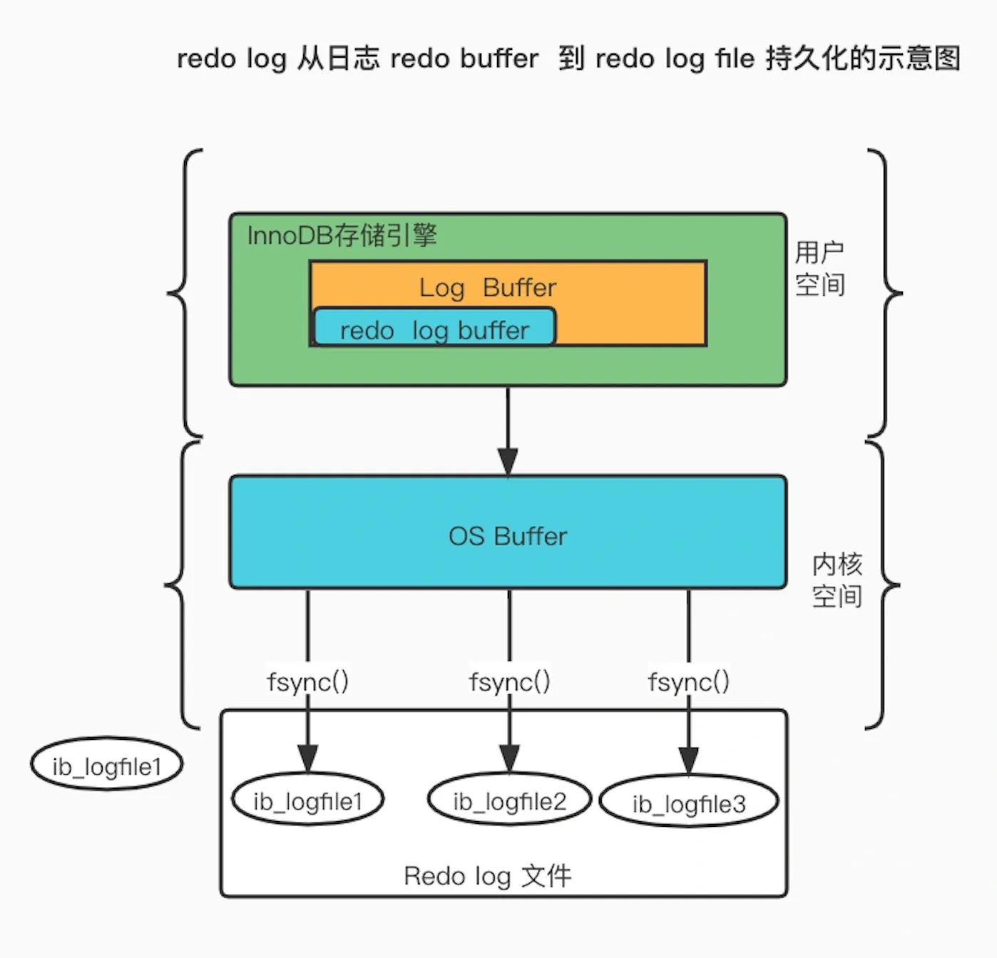
- What is the process for writing generated redo log to disk?
Redo log has its own cache — the redo log buffer (default 16MB): Whenever a redo log entry is generated, it is first written to this buffer, and later persisted to disk.
- When is redo log flushed to disk?
- When MySQL shuts down normally.
- When the amount of records written to the redo log buffer exceeds half of its capacity.
- By a background thread every 1 second.
- At every transaction commit.
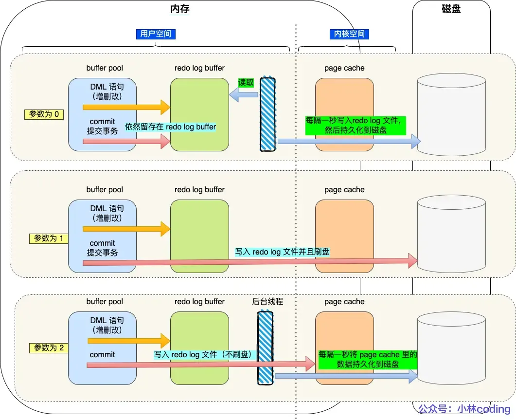
The flush strategy is mainly controlled by the parameter
innodb_flush_log_at_trx_commit:
- Parameter = 0: Does not actively trigger write-to-disk operations.
- Parameter = 1: Persists to disk at every transaction commit.
- Parameter = 2: At every transaction commit, writes the redo log from the redo log buffer to the Page Cache.
- Page Cache is dedicated to caching file data and is an operating system-level cache (i.e., outside the MySQL process lifecycle).
- Page Cache is dedicated to caching file data and is an operating system-level cache (i.e., outside the MySQL process lifecycle).
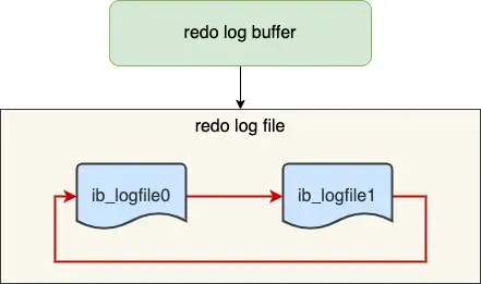
Redo Log File Group & Circular Writing#
The redo log file group works in a circular write manner.
Assuming two files:
ib_logfile0 and ib_logfile1Writing starts from the beginning, and when the end is reached, it wraps back to the start, forming a ring.
When dirty pages in the buffer pool are flushed to disk, the corresponding records in the redo log become useless. At this point, these records can be erased to free up space.

write posindicates the current write position.checkpointindicates the position to be erased next.- The red part represents new update operations.
- The blue part represents records of dirty data pages waiting to be flushed.
If the red part is full, it means the redo log is full. At this point, no new update operations can be executed (i.e., MySQL will be blocked), waiting for dirty pages in the buffer pool to be flushed to disk (marking which records can be erased). Once space is freed up by erasing old redo log records, the
checkpointmoves forward, allowing new update operations to resume.
Binlog - MySQL#
When MySQL completes an update operation, it generates a binlog entry. After the transaction commits, all binlog entries are written uniformly to the binlog file.
It records all database table structure changes or data modifications (does not log query operations).
Differences between redo log and binlog? Why do both need to exist simultaneously?#
- Binlog is a log implemented at the MySQL server layer, while redo log is implemented by the InnoDB storage engine.
- Writing Method: Redo log uses circular writing with a fixed space size; binlog uses appending, never overwriting previous logs, preserving full logs.
- Purpose: Redo log is for crash recovery; binlog is for backup recovery and master-slave replication.
- File Format: Redo log is a physical log (as above); binlog has three format types:
STATEMENT(logical log & default): Every SQL statement that modifies data is recorded in the binlog.ROW: Records what the final modification looked like (changes to every row of data are recorded, which can easily lead to very large binlog files).MIXED: A hybrid of the previous two; switches between the two formats based on the situation.
Can redo log be used to recover an entire deleted database?
No. Because redo log uses circular writing with a fixed size, it keeps writing and erasing logs, only recording physical logs that haven’t been flushed to disk yet.
Binlog is used here because it stores full logs, preserving all data change history. Any data recorded in the binlog can be recovered. If the entire database is deleted, data can be restored using the binlog.
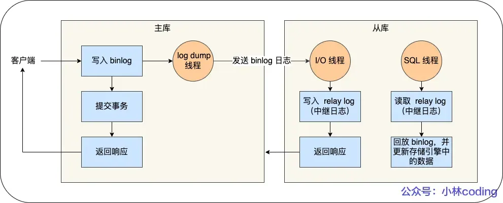
Master-Slave Replication:#
Detailed process:
- Write to Binlog: The master receives a client request, writes to its binlog, commits the transaction, and then sends an “operation successful” response to the client.
- Slave I/O Thread: The slave creates a dedicated I/O thread that connects to the master’s log dump thread to receive the master’s binlog. It writes the received binlog to its relay log and then sends a “replication successful” response back to the master.
- Slave SQL Thread: The slave creates a thread to read the relay log and replay the binlog events to update its data, ensuring data consistency between master and slave.
With a master-slave structure, writes can be directed to the master and reads to the slave(s). Even if a table or record is locked on the master, read requests on the slave are not affected.
Typically, a setup includes 1 master, 2 slaves, and 1 standby master.
Master-Slave Replication Modes:
- Synchronous Replication: The master waits for acknowledgment of successful replication from all slaves before returning the result to the client.
- Asynchronous Replication (Default): The master returns the result without waiting for the binlog to be synchronized to the slaves. If the master crashes, data loss can occur.
- Semi-synchronous Replication: A compromise between synchronous and asynchronous. The master waits for acknowledgment from at least one slave (or a configurable number) before returning. (Seems quite good).
How is Binlog Flushed to Disk?#
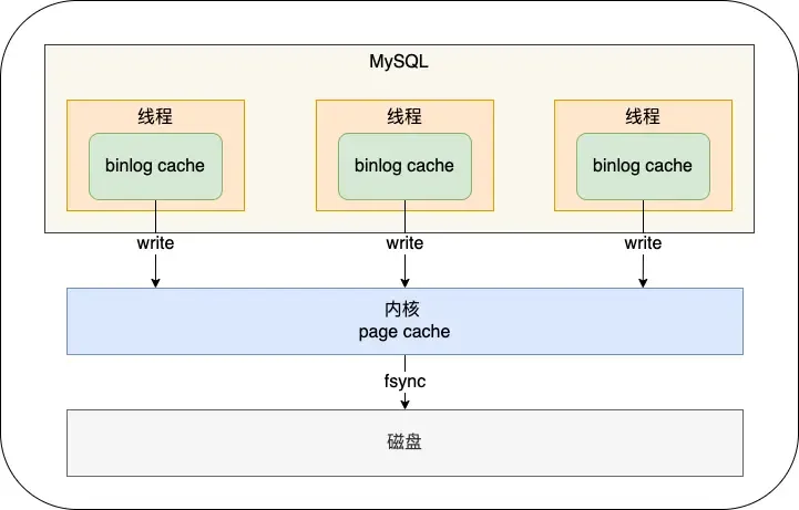 During transaction execution, logs are first written to the
 binlog cache (size determined by binlog_cache_size). At transaction commit, the contents of the binlog cache are written to the binlog file.
A transaction’s binlog cannot be split, otherwise, it would break transaction atomicity.
The sync_binlog parameter controls the frequency of flushing binlog to disk:
0(default): At each commit, onlywrite(to OS cache) is performed, notfsync. The OS decides when to persist to disk later.1: At each commit,writeand then immediatelyfsyncare performed.N(N>1): At each commit,writeis performed, butfsyncis only done after accumulating N transactions.
Two-Phase Commit#
Both binlog and redo log need to be persisted to disk. However, because the logic for these two logs is separate, there’s a possibility that one succeeds and the other fails (semi-success), leading to data inconsistency.
Therefore, we need to avoid this problem by ensuring that either both logs succeed or both fail (i.e., a distributed transaction consistency protocol).
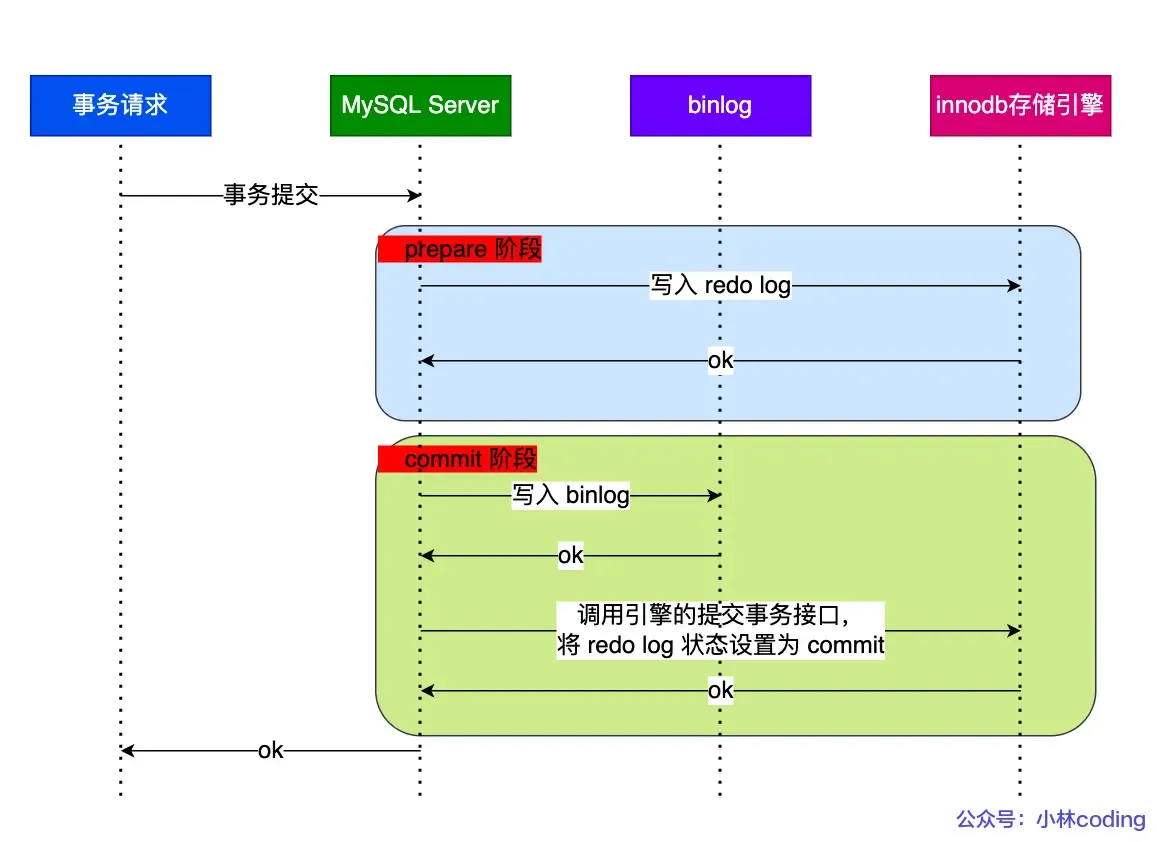 Transaction commit is divided into two phases: (A bit confusing)
- Prepare Phase: Writes the XID (internal XA transaction ID) to the redo log, sets the redo log transaction state to
prepare, and persists the redo log to disk. - Commit Phase: Writes the XID to the binlog, persists the binlog to disk, and then calls the transaction commit interface to set the redo log state to
commit. The redo log here mainly needs to bewriten to the page cache. Since the binlog write to disk was successful, even if the redo log state isprepare, the transaction is still considered successful.
If an abnormal restart occurs after a crash, the recovery process mainly uses whether the binlog was successfully written as the indicator of a successful transaction commit. If the binlog was written successfully, it can find the same XID in the redo log.
The description of two-phase commit above aims to solve the “semi-success” problem between redo log and binlog.
Problems with Two-Phase Commit:#
High Disk I/O Count: For two-phase commit, the default “double 1” configuration (parameters set to 1) results in two disk flushes per transaction commit (redo log and binlog).
Double 1: sync_binlog=1 and innodb_flush_at_trx_commit=1.
These settings mean: at each transaction commit, the binlog cache is directly persisted to disk, and the redo log buffer is persisted to disk. (i.e., both logs are flushed at commit time, leading to low efficiency).
Intense Lock Contention: Two-phase commit ensures the content of the two logs is consistent, but it cannot guarantee consistent commit order across multiple transactions. Therefore, a lock is needed to ensure commit atomicity and maintain sequential order.
Locking solves the order consistency problem, but under high concurrency, it leads to fierce lock contention and poor performance. (The lock’s lifecycle here: Acquire the lock to enter the prepare phase; release the lock only after the commit phase ends.)
Group Commit for Binlog/Redo Log#
Binlog Group Commit: Merges multiple binlog flush operations into one, thereby reducing the number of disk I/O operations.
For example, flushing 10 transactions together reduces the cost from 10 to nearly 1.
For binlog group commit, the commit phase is split into three parts:
- Flush Phase: Multiple transactions, in the order they arrived, write their binlog from cache to the file (but do not flush/fsync).
- Sync Phase: Performs an
fsyncoperation on the binlog file (i.e., merges the flush of multiple transactions’ binlogs into one disk write). - Commit Phase: Transactions, in order, perform the InnoDB commit operation. Compared to the two-phase locking approach above, the advantage is that the transaction commit process is no longer locked entirely. The lock granularity is reduced, allowing multiple phases to execute concurrently.
Redo Log Group Commit: (Introduced in MySQL 5.7) Transactions no longer flush the redo log to disk during the prepare phase. Instead, this is deferred to the Flush Phase. By delaying the write, redo log achieves a form of group write.
(Originally, redo log flush occurred immediately after the prepare phase completed, so each redo log was flushed sequentially, which was inefficient. With redo log group commit, flushing is moved to the Flush phase, flushing a group of redo logs at once, thus reducing disk I/O cost.)
Summarizing Each Phase of Group Commit#
Flush Phase:
1. The first transaction to arrive becomes the leader, subsequent ones become followers.
2. Acquire the transaction group. The leader performs one `write` + `fsync` for the group's redo logs, flushing the entire group's redo log at once.
3. Write the binlogs generated by this group of transactions to the binlog file (calls `write`, but not `fsync`).
> The Flush phase supports redo log group commit.Sync Phase:
1. After this group's binlogs are written, they are not flushed (`fsync`) immediately. Instead, the system waits for a period (`binlog_group_commit_sync_delay`). The purpose is to allow as many subsequent transactions as possible to join the group for a single flush. However, if the waiting period is cut short by reaching `binlog_group_commit_sync_no_delay_count` early, the binlog is flushed immediately without waiting further.

> The Sync phase supports binlog group commit.

The two parameters: the first sets the wait time in microseconds, the second sets the maximum number of transactions to wait for.If the database crashes after this step, the binlog already contains the transactions. Upon restart, MySQL will use the data flushed by the redo log to proceed with committing the transactions.
Commit Phase:
Calls the engine’s commit interface to set the redo log state to commit.
This phase takes over the transactions from the Sync phase, completing the final engine commit, allowing the Sync phase to process the next group of transactions quickly.
MySQL Disk I/O Optimization Methods:#
Controlling parameters:
- Use two parameters to delay the flush timing, minimizing the number of flushes (but potentially increasing response time):
binlog_group_commit_sync_delay and binlog_group_commit_sync_no_delay_count- Control parameter:
Set sync_binlog to a value greater than 1: `write` at each commit, but `fsync` only after accumulating N transactions. This delays binlog flush (but if the host crashes, binlog for the last N transactions could be lost).- Control parameter:
Set innodb_flush_log_at_trx_commit to 2: `write` at each commit but no `fsync` (host crash can lead to data loss).Now, let’s try to review the detailed execution process of an
UPDATEstatement?
About MySQL Locking Mechanism: How are Locks Added?#
We’ve covered unique indexes; can summarize later!
We can use
select * from performance_schema.data_locks\G;to view the locks acquired during SQL execution.
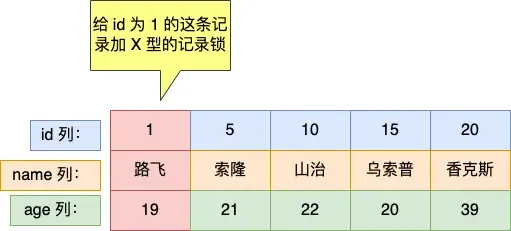
For Unique Index Equality Queries:#
mysql> select * from user where id = 1 for update;If the record exists: Degenerates to a record lock.
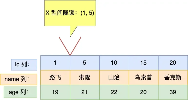
mysql> select * from user where id = 2 for update;If the record does not exist: Degenerates to a gap lock.
For Unique Index Range Queries*:#
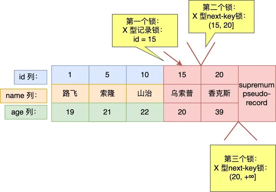
mysql> select * from user where id > 15 for update;For greater-than operations:
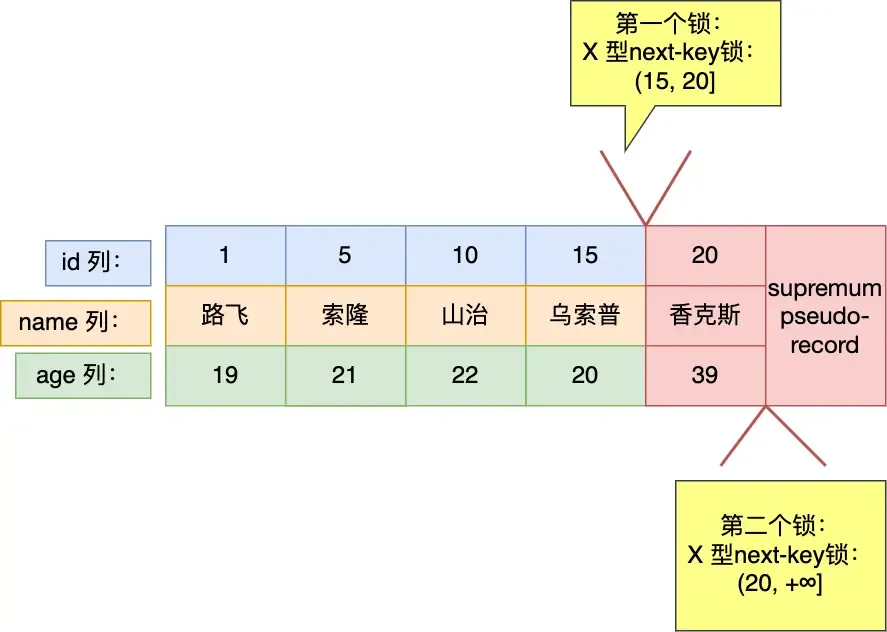
mysql> select * from user where id >= 15 for update;For greater-than-or-equal operations:
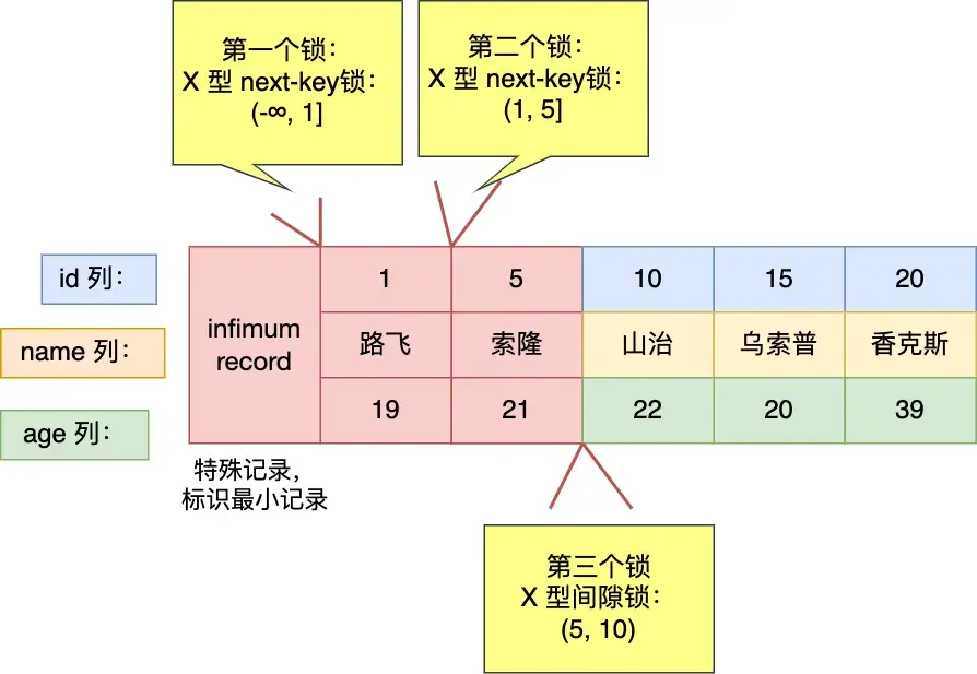
mysql> select * from user where id < 6 for update;For less-than operations:
- If the queried value does not exist in the table (as shown here).
- If the queried value exists in the table (e.g., query for
id < 5), it would differ, resulting in(-∞, 5).- My feeling is that 5 is already outside the range, so it shouldn’t be considered. But MySQL still does.
I think this could be an optimization point: when
id < targetand the target is 1 greater than the maximum ID in the table, the right side could be ignored, but MySQL still considers it.
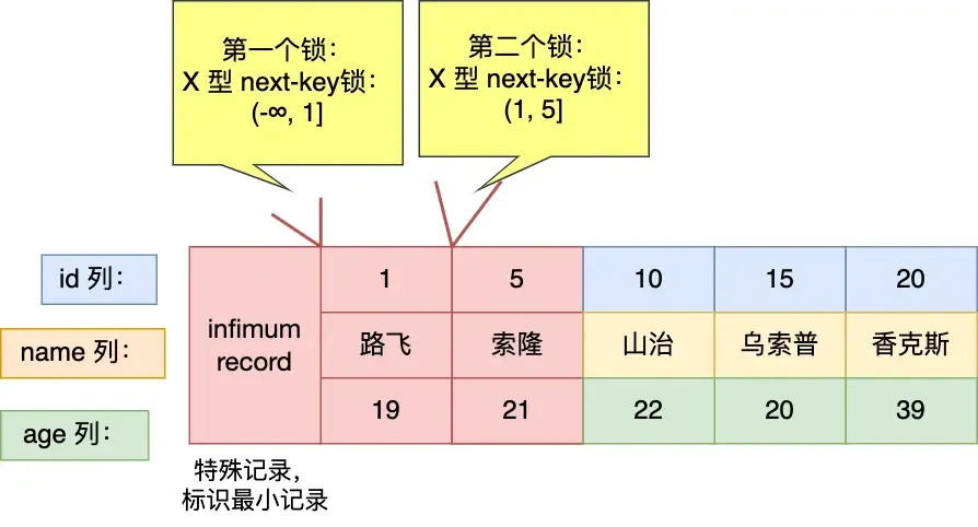
mysql> select * from user where id <= 5 for update;==Question: Why isn’t a record lock added for
id=5here? In the previous example, it was added?==
For Non-Unique Index Equality Queries:#
select * from user where age = 25 for update;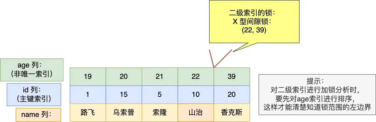
For this query, a gap lock (22, 39) is added. Whether insertion at the boundaries succeeds depends on the primary key value! (If the value falls within the locked range considering both index and PK, it’s blocked; otherwise, it succeeds.) For boundary 22:
- Inserting
(22, 3)can succeed. - Inserting
(22, 12)will be blocked. For boundary 39 (opposite of 22): - Inserting
(39, 3)will be blocked. - Inserting
(39, 12)can succeed.
mysql> select * from user where age = 22 for update;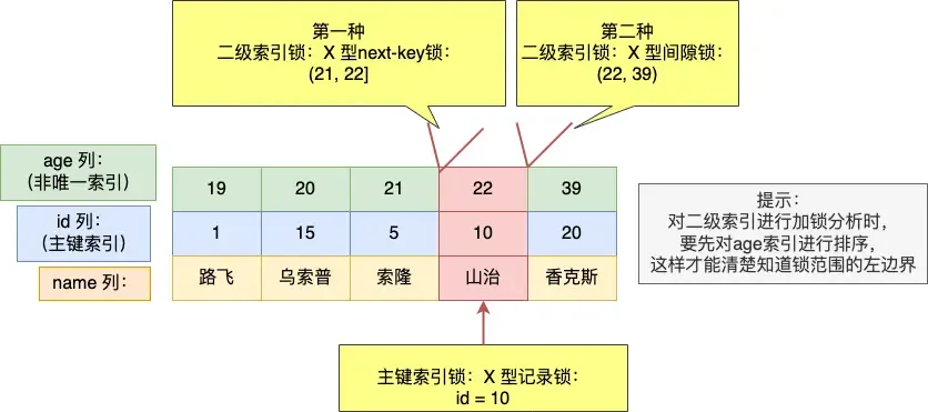
Three locks are added here (can be seen as merged intervals):
- next-key lock:
(21, 22] - gap lock:
(22, 39) - primary key record lock:
id=10
Need to pay attention to the boundary issues here as well!
Regarding the X locks added on the two secondary indexes:
- For the next-key lock:
- If a value inserted during this period falls between the boundaries (here “between” refers to the combination of secondary index and primary key), the insert is blocked. Otherwise, it might succeed (though other conflicting conditions must also be considered).
- For example, inserting
(22, 12)meets the condition, but it is still bound by the gap lock, so it cannot be inserted successfully.
- For the gap lock:
- Same as above, but a comprehensive consideration is needed.
Why is a gap lock needed here? Could phantom reads be prevented without it?
Without it, phantom reads cannot be prevented. The added next-key lock interval is (21, 22]. If a record (22, 12) is inserted, it falls outside this interval, potentially causing a phantom read if queried later.
For Non-Unique Index Range Queries:#
Here, the next-key lock does not degrade!
mysql> select * from user where age >= 22 for update;
Personally, I feel I understand the concept. It can be understood like this: The essence is to ensure that re-querying does not yield inconsistent results. So, we must guarantee this.
- For data found (secondary index records), we need to ensure that records with the same secondary index value but any primary key value cannot be inserted again. So, we need to “cover a bit more” on both sides to guarantee consistency on re-query.
- For data not found, no such guarantee is needed (though this sounds like stating the obvious).
For Queries Without an Index:#
No index, so full table scan is used directly. Every record encountered will have a next-key lock applied. Insert, update, and delete operations on these records will be blocked.
Similarly, UPDATE and DELETE statements without indexes also perform full table scans.
Therefore, always try to make statements use indexes; otherwise, they are very slow.
Deadlocks in MySQL#
Example:
Database table:
CREATE TABLE `t_student` (
  `id` int NOT NULL,
  `no` varchar(255) DEFAULT NULL,
  `name` varchar(255) DEFAULT NULL,
  `age` int DEFAULT NULL,
  `score` int DEFAULT NULL,
  PRIMARY KEY (`id`)
) ENGINE=InnoDB DEFAULT CHARSET=utf8mb4;Insert data:

Start two transactions:

This essentially illustrates the conflict between gap locks and insert intention locks. (Gap locks do not conflict with each other, but a gap lock and an insert intention lock do conflict.)